Run lvl span calculator
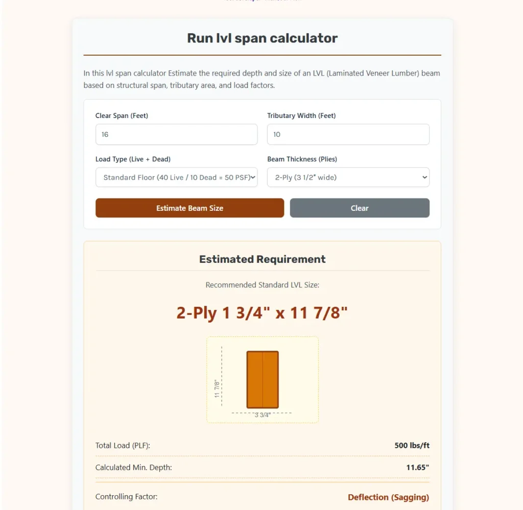
In this lvl span calculator Estimate the required depth and size of an LVL (Laminated Veneer Lumber) beam based on structural span, tributary area, and load factors.
Understanding Beam Calculations
What is Tributary Width?
Tributary width is the area of the floor or roof that structurally rests on the beam. For a center beam holding up joists that span 12 feet on one side and 10 feet on the other, the tributary width is half of each side combined (6 + 5 = 11 feet).
The Math Behind the Depth
Beams generally fail or feel “bouncy” due to two limits: Bending Moment (snapping) or Deflection (sagging). The estimator calculates the required depth for both and recommends the larger size.
w = Load (PSF) × Tributary Width
Moment (M) = w × Span2 × 1.5
Req. Depth for Bending = √( (6 × M / Fb) / width )
Standard LVL Sizes
Most manufacturers produce LVLs in thicknesses of 1 3/4″ per ply, and in standard depth increments: 5 1/2″, 7 1/4″, 9 1/4″, 11 7/8″, 14″, 16″, 18″, and 24″. If your required depth exceeds 24″, you must increase the number of plies (width) to bring the required depth down.
Structural Design of Laminated Veneer Lumber Beams: Span Mechanics, Load Formulations, and Engineering Underwriting
In modern structural framing, the ability to create wide, open architectural spaces depends directly on the performance of engineered wood products. While traditional solid-sawn lumber is limited by the natural growth characteristics of trees, engineered wood products provide a predictable, high-strength alternative. Among these materials, Laminated Veneer Lumber (LVL) serves as a primary choice for header, girder, and ridge beam installations.
Sizing an LVL beam requires a detailed understanding of structural mechanics, load paths, and material science. A specialized LVL span calculator operates as an essential preliminary design tool. By evaluating structural span, tributary width, load types, and multi-ply configurations, these utilities allow builders, framing contractors, and designers to estimate appropriate member sizes. This guide provides an in-depth analysis of the mathematical formulations, physical principles, and regulatory standards that govern the engineering of LVL beams.
The Engineering Philosophy of Laminated Veneer Lumber
To appreciate the mathematical models used to size an LVL beam, we must examine the manufacturing process and material properties that set engineered wood apart from solid-sawn lumber.
1. Wood as a Natural Anisotropic Material
Solid-sawn timber is anisotropic, meaning its physical properties differ depending on grain orientation. It is also subject to natural growth defects, including:
- Knots, which disrupt the continuity of wood fibers and reduce tension strength.
- Splits, checks, and shakes, which weaken the shear capacity of the member.
- Slope of grain, where grain deviation reduces overall flexural strength.
2. The Homogenization of Wood Fiber
LVL manufacturing overcomes these natural limitations by peeling logs into thin veneers (typically $1/10$ to $1/8$ inch thick). These veneers are dried, graded ultrasonically for stiffness, and coated with waterproof adhesive. They are then laid up in a parallel-lamination configuration and pressed under intense heat and pressure to form large billets.
This parallel-grain structure provides several key engineering benefits:
$\checkmark$ Defect Dispersion: Natural defects like knots are randomized and spread throughout the cross-section, preventing any single flaw from compromising the strength of the beam.
$\checkmark$ Moisture Uniformity: Veneers are dried uniformly before assembly, making LVL highly resistant to warping, twisting, shrinking, and crowning on the jobsite.
$\checkmark$ Dimensional Stability: The high density of the composite material provides an allowable bending stress ($F_b$) and modulus of elasticity ($E$) that far exceed those of traditional framing lumber.
Fundamentals of Structural Load Paths and Tributary Areas
Before calculating the required size of a carrying beam, we must determine the exact amount of weight that the member is required to support. This process begins by establishing the load path and defining the tributary area.
1. Understanding the Tributary Width
The tributary area represents the surface area of a floor or roof that transfers its weight directly to a specific structural member. The tributary width ($W_{\text{trib}}$) is the linear width of that area.
For a simply supported floor joist system:
- Joists span between an exterior load-bearing wall and an interior carrying beam.
- The interior beam supports half of the span of the joists on its left, and half of the span of the joists on its right.
The tributary width is calculated as:$$W_{\text{trib}} = \frac{L_{\text{left}}}{2} + \frac{L_{\text{right}}}{2}$$
Where:
- $\rightarrow$ $W_{\text{trib}}$ represents the total Tributary Width in feet.
- $\rightarrow$ $L_{\text{left}}$ represents the joist span to the left of the beam in feet.
- $\rightarrow$ $L_{\text{right}}$ represents the joist span to the right of the beam in feet.
2. Area Loads vs. Line Loads
Building codes define structural design loads in pounds per square foot (PSF), which is an area-based metric. To size a beam, we must convert this area load into a line load, expressed in pounds per linear foot (PLF). This represents the weight concentrated along each foot of the beam’s span.
Primary Variables in Structural Beam Sizing
To estimate the required depth of an LVL member, a structural designer must analyze four primary operational variables.
1. Clear Span
The clear span represents the horizontal distance between the inside faces of the beam’s supports. This represents the unsupported length of the beam and is the most sensitive variable in bending and deflection calculations.
2. Tributary Width
The width of the floor or roof area that transfers load directly to the beam, measured in feet.
3. Design Load Type
The combined live load (temporary forces like occupants, furniture, or snow) and dead load (permanent weight of the building materials) acting on the structure. Common standard design loads include:
- Standard Roof Load ($40\text{ PSF}$): Typically composed of $30\text{ PSF}$ live load (snow/wind) and $10\text{ PSF}$ dead load (shingles, rafters, drywall).
- Standard Floor Load ($50\text{ PSF}$): Typically composed of $40\text{ PSF}$ live load (occupants/furniture) and $10\text{ PSF}$ dead load (subfloor, joists, finishes).
- Heavy Floor/Tile Load ($65\text{ PSF}$): Typically used when heavy flooring materials, like thick mortar beds or stone tiles, are specified.
- Commercial/Deck Load ($80\text{ PSF}$): Designed to accommodate higher public occupancy or heavy exterior deck loads.
4. Beam Thickness (Plies)
LVL beams are manufactured in standard thicknesses of $1\ \frac{3}{4}$ inches per ply. To increase the load-carrying capacity of a beam, multiple plies are fastened together side-by-side on the jobsite.
- 1-Ply: $1\ \frac{3}{4}$ inches wide ($1.75$ inches).
- 2-Ply: $3\ \frac{1}{2}$ inches wide ($3.50$ inches).
- 3-Ply: $5\ \frac{1}{4}$ inches wide ($5.25$ inches).
- 4-Ply: $7$ inches wide ($7.00$ inches).
Mathematical Architecture of Beam Sizing
To ensure perfect legibility on mobile devices and small screen containers, the engineering equations for flexural strength and deflection serviceability are broken down into narrow, vertically stacked steps.
These equations use standard design values for premium grade $2.0\text{E}$ LVL:
- Modulus of Elasticity ($E$) = $2,000,000\text{ psi}$
- Allowable Bending Stress ($F_b$) = $2,600\text{ psi}$
1. Line Load Conversion
The first step converts the area design load from pounds per square foot (PSF) to a linear load along the beam.$$w_{\text{plf}} = W_{\text{trib}} \times L_{\text{psf}}$$
Where:
- $\rightarrow$ $w_{\text{plf}}$ represents the linear load in pounds per foot.
- $\rightarrow$ $W_{\text{trib}}$ represents the Tributary Width in feet.
- $\rightarrow$ $L_{\text{psf}}$ represents the combined area design load in PSF.
To perform engineering calculations, this linear load must be scaled to pounds per linear inch (PLI):$$w_{\text{pli}} = \frac{w_{\text{plf}}}{12}$$
Where:
- $\rightarrow$ $w_{\text{pli}}$ represents the linear load in pounds per inch.
- $\rightarrow$ $w_{\text{plf}}$ represents the linear load in pounds per foot.
2. Conversion of Span to Inches
The horizontal clear span must be converted from feet to inches:$$L_{\text{in}} = S_{\text{ft}} \times 12$$
Where:
- $\rightarrow$ $L_{\text{in}}$ represents the clear span in inches.
- $\rightarrow$ $S_{\text{ft}}$ represents the clear span in feet.
3. Bending Moment Calculation
For a simply supported beam with a uniformly distributed load, the maximum bending moment occurs at the exact center of the span.$$M = \frac{w_{\text{pli}} \times L_{\text{in}}^2}{8}$$
Where:
- $\rightarrow$ $M$ represents the maximum bending moment in inch-pounds.
- $\rightarrow$ $w_{\text{pli}}$ represents the linear load in pounds per inch.
- $\rightarrow$ $L_{\text{in}}$ represents the clear span in inches.
4. Required Section Modulus (Bending Strength)
The section modulus ($S$) represents the geometric property of a beam’s cross-section that resists bending stresses. The minimum required section modulus is determined by dividing the maximum moment by the allowable bending stress.$$S_{\text{req}} = \frac{M}{F_b}$$
Where:
- $\rightarrow$ $S_{\text{req}}$ represents the required section modulus in inches cubed.
- $\rightarrow$ $M$ represents the calculated bending moment in inch-pounds.
- $\rightarrow$ $F_b$ represents the allowable bending stress of the material ($2,600\text{ psi}$).
5. Required Depth for Bending Strength
For a rectangular beam, the section modulus is defined as:$$S = \frac{b \times d^2}{6}$$
By rearranging this equation, we can calculate the minimum required depth ($d_{\text{bend}}$) to satisfy bending strength requirements:$$d_{\text{bend}} = \sqrt{\frac{6 \times S_{\text{req}}}{b}}$$
Where:
- $\rightarrow$ $d_{\text{bend}}$ represents the minimum required depth for strength in inches.
- $\rightarrow$ $S_{\text{req}}$ represents the required section modulus in inches cubed.
- $\rightarrow$ $b$ represents the total width of the beam in inches (plies $\times 1.75$ inches).
6. Maximum Allowable Deflection Limit
Under standard building codes, a structural beam must be stiff enough to prevent excessive sagging (deflection). The standard deflection limit for total design load is $1/240$ of the span.$$\Delta_{\text{allow}} = \frac{L_{\text{in}}}{240}$$
Where:
- $\rightarrow$ $\Delta_{\text{allow}}$ represents the maximum allowable deflection in inches.
- $\rightarrow$ $L_{\text{in}}$ represents the clear span in inches.
7. Required Moment of Inertia (Deflection Control)
The moment of inertia ($I$) represents a cross-section’s resistance to rotational or bending deformation. For a simply supported beam under a uniform load, the deflection is defined as:$$\Delta = \frac{5 \times w_{\text{pli}} \times L_{\text{in}}^4}{384 \times E \times I}$$
By rearranging this formula, we can determine the minimum required moment of inertia ($I_{\text{req}}$) needed to keep deflection within the allowable limit:$$I_{\text{req}} = \frac{5 \times w_{\text{pli}} \times L_{\text{in}}^4}{384 \times E \times \Delta_{\text{allow}}}$$
Where:
- $\rightarrow$ $I_{\text{req}}$ represents the required moment of inertia in inches to the fourth power.
- $\rightarrow$ $w_{\text{pli}}$ represents the linear load in pounds per inch.
- $\rightarrow$ $L_{\text{in}}$ represents the clear span in inches.
- $\rightarrow$ $E$ represents the material’s Modulus of Elasticity ($2,000,000\text{ psi}$).
- $\rightarrow$ $\Delta_{\text{allow}}$ represents the maximum allowable deflection in inches.
8. Required Depth for Deflection Control
For a rectangular beam, the moment of inertia is defined as:$$I = \frac{b \times d^3}{12}$$
By rearranging this equation, we can calculate the minimum required depth ($d_{\text{defl}}$) to satisfy the deflection limit:$$d_{\text{defl}} = \sqrt[3]{\frac{12 \times I_{\text{req}}}{b}}$$
Where:
- $\rightarrow$ $d_{\text{defl}}$ represents the minimum required depth for stiffness in inches.
- $\rightarrow$ $I_{\text{req}}$ represents the required moment of inertia in inches to the fourth power.
- $\rightarrow$ $b$ represents the total width of the beam in inches (plies $\times 1.75$ inches).
9. Establishing the Controlling Depth
The final step compares the required depths for strength and stiffness. The larger of the two values controls the design:$$d_{\text{control}} = \max(d_{\text{bend}}, d_{\text{defl}})$$
Where:
- $\rightarrow$ $d_{\text{control}}$ represents the controlling minimum depth of the beam.
- $\rightarrow$ $d_{\text{bend}}$ represents the required depth for bending strength.
- $\rightarrow$ $d_{\text{defl}}$ represents the required depth for deflection control.
The Deflection vs. Strength Conflict: What Controls Sizing?
A key concept in structural engineering is that beams are often limited by stiffness (deflection) rather than actual material strength.
- Short Spans (Strength-Controlled): On shorter spans, bending stress and shear stress are typically the limiting factors. The beam is highly resistant to sagging, so strength requirements dictate the depth.
- Long Spans (Deflection-Controlled): On longer spans, the bending moment increases with the square of the span ($L^2$), while the deflection increases with the fourth power of the span ($L^4$). As a result, deflection becomes the controlling factor on long spans, meaning a beam must often be sized larger simply to prevent it from feeling bouncy or sagging over time.
Standard LVL Sizes and Properties
Laminated Veneer Lumber is manufactured in standard depths that match standard framing dimensions. If the controlling calculated depth falls between two standard sizes, you must round up to the next available standard depth.
The table below outlines standard depths, widths, and the corresponding structural properties for a $2$-ply ($3.50$ inches wide) beam configuration:
| Standard Depth (d) | Width (2-Ply) | Cross-Sectional Area | Section Modulus (S) | Moment of Inertia (I) |
| $5.50\text{ in}$ | $3.50\text{ in}$ | $19.25\text{ in}^2$ | $17.65\text{ in}^3$ | $48.53\text{ in}^4$ |
| $7.25\text{ in}$ | $3.50\text{ in}$ | $25.38\text{ in}^2$ | $30.67\text{ in}^3$ | $111.17\text{ in}^4$ |
| $9.25\text{ in}$ | $3.50\text{ in}$ | $32.38\text{ in}^2$ | $49.91\text{ in}^3$ | $230.85\text{ in}^4$ |
| $11.25\text{ in}$ | $3.50\text{ in}$ | $39.38\text{ in}^2$ | $73.83\text{ in}^3$ | $415.28\text{ in}^4$ |
| $11.875\text{ in}$ | $3.50\text{ in}$ | $41.56\text{ in}^2$ | $82.25\text{ in}^3$ | $488.37\text{ in}^4$ |
| $14.00\text{ in}$ | $3.50\text{ in}$ | $49.00\text{ in}^2$ | $114.33\text{ in}^3$ | $800.33\text{ in}^4$ |
| $16.00\text{ in}$ | $3.50\text{ in}$ | $56.00\text{ in}^2$ | $149.33\text{ in}^3$ | $1,194.67\text{ in}^4$ |
| $18.00\text{ in}$ | $3.50\text{ in}$ | $63.00\text{ in}^2$ | $189.00\text{ in}^3$ | $1,701.00\text{ in}^4$ |
| $24.00\text{ in}$ | $3.50\text{ in}$ | $84.00\text{ in}^2$ | $336.00\text{ in}^3$ | $4,032.00\text{ in}^4$ |
Real-World Design Case Studies
To see how these formulas apply in practice, we can analyze two detailed structural scenarios: a standard residential floor opening and a larger premium ridge beam.
Case Study A: Standard Residential Floor Opening
A contractor is opening a wall between a kitchen and living room, requiring a new carrying beam to support standard residential floor joists.
- $\rightarrow$ Clear Span ($S_{\text{ft}}$) = $16.00\text{ feet}$
- $\rightarrow$ Tributary Width ($W_{\text{trib}}$) = $10.00\text{ feet}$
- $\rightarrow$ Design Load Type = $50\text{ PSF}$ (Floor Load)
- $\rightarrow$ Target Thickness = $2$-Ply ($b = 3.50\text{ inches}$)
Step 1: Calculate Linear Loads and Clear Span
- Clear span in inches:
$$L_{\text{in}} = 16 \times 12 = 192\text{ inches}$$ - Linear load in PLF:
$$w_{\text{plf}} = 10.00 \times 50 = 500\text{ PLF}$$ - Linear load in PLI:
$$w_{\text{pli}} = \frac{500}{12} \approx 41.67\text{ PLI}$$
Step 2: Evaluate Bending Strength
- Bending moment $M$:
$$M = \frac{41.67 \times 192^2}{8}$$$$M = \frac{41.67 \times 36,864}{8}$$$$M \approx 192,015.36\text{ in-lbs}$$ - Required section modulus:
$$S_{\text{req}} = \frac{192,015.36}{2,600} \approx 73.85\text{ in}^3$$ - Required depth for bending:
$$d_{\text{bend}} = \sqrt{\frac{6 \times 73.85}{3.5}}$$$$d_{\text{bend}} = \sqrt{\frac{443.10}{3.5}}$$$$d_{\text{bend}} \approx 11.25\text{ inches}$$
Step 3: Evaluate Deflection Serviceability
- Allowable deflection limit:
$$\Delta_{\text{allow}} = \frac{192}{240} = 0.80\text{ inches}$$ - Required moment of inertia:
$$I_{\text{req}} = \frac{5 \times 41.67 \times 192^4}{384 \times 2,000,000 \times 0.80}$$$$I_{\text{req}} = \frac{5 \times 41.67 \times 1,358,954,496}{614,400,000}$$$$I_{\text{req}} \approx 460.80\text{ in}^4$$ - Required depth for deflection:
$$d_{\text{defl}} = \sqrt[3]{\frac{12 \times 460.80}{3.5}}$$$$d_{\text{defl}} = \sqrt[3]{\frac{5,529.60}{3.5}}$$$$d_{\text{defl}} = \sqrt[3]{1,579.89}$$$$d_{\text{defl}} \approx 11.65\text{ inches}$$
Step 4: Establish the Controlling Depth and Recommend Size
Comparing the required depths:
- $d_{\text{bend}} = 11.25\text{ inches}$
- $d_{\text{defl}} = 11.65\text{ inches}$
Deflection controls the design ($11.65\text{ inches} > 11.25\text{ inches}$). Rounding up to the next available standard size yields $11\ \frac{7}{8}$ inches ($11.875$ inches).
The recommended beam size is: 2-Ply 1 3/4″ x 11 7/8″.
Case Study B: Premium Great Room Roof Ridge Beam
A designer plans a cathedral ceiling in a great room, requiring a structural ridge beam to support a standard roof load.
- $\rightarrow$ Clear Span ($S_{\text{ft}}$) = $20.00\text{ feet}$
- $\rightarrow$ Tributary Width ($W_{\text{trib}}$) = $12.00\text{ feet}$
- $\rightarrow$ Design Load Type = $40\text{ PSF}$ (Roof Load)
- $\rightarrow$ Target Thickness = $3$-Ply ($b = 5.25\text{ inches}$)
Step 1: Calculate Linear Loads and Clear Span
- Clear span in inches:
$$L_{\text{in}} = 20 \times 12 = 240\text{ inches}$$ - Linear load in PLF:
$$w_{\text{plf}} = 12.00 \times 40 = 480\text{ PLF}$$ - Linear load in PLI:
$$w_{\text{pli}} = \frac{480}{12} = 40.00\text{ PLI}$$
Step 2: Evaluate Bending Strength
- Bending moment $M$:
$$M = \frac{40.00 \times 240^2}{8}$$$$M = \frac{40.00 \times 57,600}{8}$$$$M = 288,000.00\text{ in-lbs}$$ - Required section modulus:
$$S_{\text{req}} = \frac{288,000.00}{2,600} \approx 110.77\text{ in}^3$$ - Required depth for bending:
$$d_{\text{bend}} = \sqrt{\frac{6 \times 110.77}{5.25}}$$$$d_{\text{bend}} = \sqrt{\frac{664.62}{5.25}}$$$$d_{\text{bend}} \approx 11.25\text{ inches}$$
Step 3: Evaluate Deflection Serviceability
- Allowable deflection limit:
$$\Delta_{\text{allow}} = \frac{240}{240} = 1.00\text{ inch}$$ - Required moment of inertia:
$$I_{\text{req}} = \frac{5 \times 40.00 \times 240^4}{384 \times 2,000,000 \times 1.00}$$$$I_{\text{req}} = \frac{200.00 \times 3,317,760,000}{768,000,000}$$$$I_{\text{req}} \approx 864.00\text{ in}^4$$ - Required depth for deflection:
$$d_{\text{defl}} = \sqrt[3]{\frac{12 \times 864.00}{5.25}}$$$$d_{\text{defl}} = \sqrt[3]{\frac{10,368.00}{5.25}}$$$$d_{\text{defl}} = \sqrt[3]{1,974.86}$$$$d_{\text{defl}} \approx 12.55\text{ inches}$$
Step 4: Establish the Controlling Depth and Recommend Size
Comparing the required depths:
- $d_{\text{bend}} = 11.25\text{ inches}$
- $d_{\text{defl}} = 12.55\text{ inches}$
Deflection controls the design ($12.55\text{ inches} > 11.25\text{ inches}$). Rounding up to the next available standard size yields $14$ inches.
The recommended beam size is: 3-Ply 1 3/4″ x 14″.
Structural Engineering Best Practices and Jobsite Auditing
Sizing a beam correctly is only half the battle. To ensure the beam performs as designed, framing crews must adhere to strict construction standards:
- Implement a Proper Fastening Pattern: Multi-ply beams must be fastened together correctly to act as a single structural unit. If plies are poorly connected, they can bend independently under load, reducing the strength of the beam. Follow manufacturer guidelines for nailing or bolting plies together.
- Verify Minimum Support Widths (Bearing): A beam must rest on a large enough support area to prevent crushing the wood fibers. Under standard codes, beams must have a minimum bearing length of $1\ \frac{1}{2}$ inches on wood supports and $3$ inches on concrete or masonry.
- Assess Lateral Torsional Buckling: Deep, narrow beams (such as a 1-ply 16-inch LVL) can twist sideways under heavy loads. Ensure the top edge of the beam is secured continuously against lateral movement by floor joists or rafters.
- Maintain Dry Service Environments: Laminated Veneer Lumber is designed for interior use only. If exposed to weather, the adhesives can degrade and the wood can rot, reducing its structural capacity. For exterior applications, specify pressure-treated solid-sawn timbers or specialty outdoor engineered glulams.
Regulatory Compliance and Building Codes
The calculations and design guidelines outlined in this document are based on the standard practices established by:
- American Wood Council (AWC). (2018). National Design Specification (NDS) for Wood Construction. ANSI/AWC NDS-2018.
- For official updates on structural wood design, engineering standards, and international residential building requirements, consult the American Wood Council (AWC) resource database or refer directly to your local International Building Code (IBC) provisions.